
May 1, 2022
Inner Circle
Control Valve Technologies in Thermoplastics
Contributed by Shane McDaniel, Business Development Manager
Asahi/America’s end users have trusted the use of our valves and actuators for critical applications in chemical, water, wastewater, ultrapure water, and oil and gas for more than 50 years. Asahi offers the broadest range of non-metallic control valves.

Control valves have a long history of application going as far back as the bronze age aqueducts of Roman Times. The late 18th century brought about the steam engine, and with it, several inventors, like James Watt, William Fisher, and William B. Mason made significant advancements in control technology.
How does an engineer decide which type of valve to select? What are the differences among all the options? What impact does this selection make on project cost and lifetime cost? How will it affect the control scheme? This article, discussing Asahi/America’s portfolio of products coupled with our engineering expertise, can help you decide.
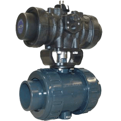
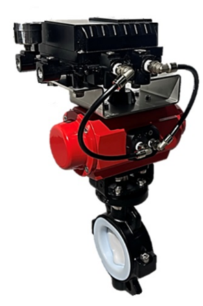
Asahi/America Type-57 butterfly valves mounted to the Series 92 electric actuator provide robust control for decades in facilities around the country. The Type-21 ball valve and Series 79 pneumatic actuator offer reliable service to OEMs and manufacturers around the globe. The Type-14 diaphragm valve provides flow control in critical slurry, abrasive environments, and dosing applications. Our PTFE valve product line offers the performance requirements of our most demanding customers and their critical application processes.
Control Valve Technologies in Thermoplastics
 As processes evolve and increase in complexity, so does the need for more advanced process controls, including the control valve. Engineers and operators are constantly looking for solutions that optimize their process toward efficient production, reliable throughput, and increased revenue. Engineers must also investigate the costs of upgrading or automating their operations and ensure their investment will see meaningful returns. Relative to the industries wherein thermoplastics are often specified and excel, best practices include new technologies, comprehensive control schemes, and an increasingly high standard for accurate flow control.
Engineers have a few questions to consider when looking at control valve options:
- What is a control valve and what does it do?
- How do I specify a control valve?
- What options or technologies are available?
What is a control valve and what will it do in the process?
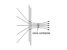
Control valves are used in processes where variables such as flow, pressure, or temperature directly impact the end result. The basic valve design allows the fluid flow to be manipulated by varying or changing the size of the flow passage or vena contracta. The vena contracta is the point in the fluid stream where the diameter of the stream is at the minimum. A valve is designed to adjust this point through the act of moving the closing member. This could be a ball, disc, or plug. They are often referred to as the final control element due to their direct physical influence on the process media.

How do I specify a control valve?
There are a number of factors to consider when looking to specify a control valve, but first, it is necessary to understand the control loop.
- What variable is being manipulated?
- Example: pressure, temperature, level
- What measurement is necessary?
- What type of control scheme is being employed?
- Example: solenoid, PLC, DCS
- What source of energy is being used?
- Example: pneumatic, electric
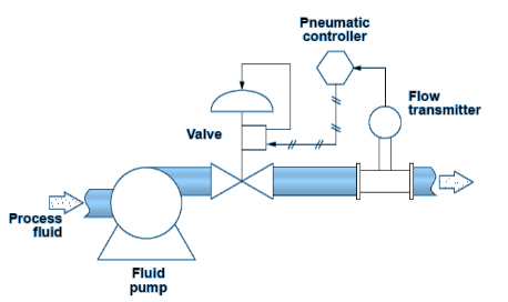
An example of a control loop might look similar to the picture on the right, with a pneumatic controller, pneumatic valve, and flow transmitter clearly identified.
It is important to understand the flow requirements of the application and how much flow is needed. As discussed before, varying the vena contracta manipulates the flow. We are interested in sizing a control valve to know how much flow will pass through the valve at any given position as its member is closing and the differential pressure (DP) created during this process.
![]()
Cv = Valve flow coefficient; Q = Fluid flow (also given by area of pipe x mean velocity); S = Specific gravity of fluid relative to water @ 60º F; ∆P = (DP) Pressure drop (P1 – P2) across the control valve at maximum flow
The relationship between DP and flow rate through a valve is expressed by a flow coefficient (Cv). Cv is defined as the number of gallons per minute (GPM) of flow that will pass through a fully open valve at 60° F, with a DP of 1psi. So, a valve with a Cv of 10 would pass 10 gallons of water in one minute with a 1psi pressure drop. For incompressible fluids like water, the equation to the left would apply.
The equation shows that the flow rate varies as the square root of the differential pressure across the control valve. The greater the pressure drop, the higher the flow rate. Pressure drop across a valve is highly influenced by the area, shape, path, and roughness of the valve, i.e., its construction or type.
Flow Control Characteristics
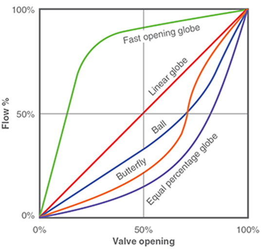
When evaluating the type of valve to utilize in your control loop, it is equally critical to understand the valve’s flow control characteristics. All valves possess an inherent flow characteristic that defines the relationship between the position of the closing member (disc, ball), and the flow rate under pressure. This is a function of the relative position of the closing member to the seat. Examples of differing characteristics are shown on the right, with various valve technologies providing an array of flow characteristics. Butterfly and full port ball valves, for example, are considered high recovery valves in that the effective rate of control between a certain percentage open and fully open is relatively small. A globe valve possesses a near-linear characteristic, giving a steady, reliable, and repeatable control across its travel.
 Aspects such as control scheme and actuation technology can impact both the process and investment decision. One of the more common schemes is a programmable logic controller (PLC) with 4-20mA positioner and feedback control loop. Other options include manual loops, where an operator adjusts the valve based on downstream information, solenoid valves operating on a voltage change, or distributed control systems (DCS) with advanced programming and communication protocols. There are also considerations relative to the valve actuation. Is the current system controlled with pneumatic or electric actuation? What type of positioner is required? Finding a control valve that meets the needs of both the process and the control scheme is critical to success.
What options or technologies are available?
While butterfly valves, ball valves, globe, and diaphragm valves have been available and in control applications for years, recent improvements to valve and actuation technologies relative to thermoplastics have led to increased capability and agility toward flow control. Advancements in actuators and controls and overall design have increased reliability, giving engineers and operators more flexibility and choices in their application process. An example of such an improvement is the recent addition of the Type-21a SST flow control valve to the Asahi portfolio.
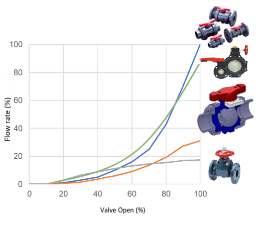
This valve is designed with all of the reliability and agility of the standard Type–21 and includes features that deliver a modified equal percentage flow characteristic, providing excellent flow control across the span of travel. The Type-21a SST can deliver these benefits at a cost-effective price point, and the serviceability of the Type-21a SST is also more attractive when compared to other valve options.
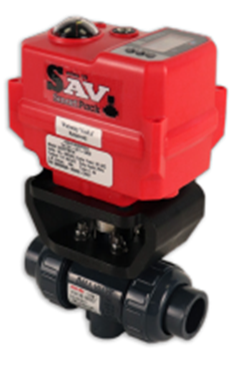 When paired with our Series 19 electric actuator, the Type-21a SST provides reliable, repeatable flow control with high setpoint accuracy, position feedback, and failsafe capability.
Engineers are looking for technologies and equipment that serve the fundamental purpose of process control in their facilities and suppliers who can provide the expertise and products that maximize productivity and solve problems that contribute to lost uptime and profitability. Whether a loop needs a simple butterfly valve with a lever operator, an automated ball valve package with a pneumatic positioner, or a specialized diaphragm valve, Asahi/America can provide the engineering and expertise for your application. Does your facility have an application that has been performing below expectations? Are you looking to upgrade or improve your current flow control scheme? Contact us today.
Learn more about our legendary valve quality and take the Type-21 challenge.
EDITOR’S NOTICE: Please note, the information in this article is for educational purposes only and does not supersede any Asahi/America technical information or product specifications. Please consult Asahi/America’s technical department at 1-800-343-3618 or pipe@asahi-america.com on all product applications in regards to material selection based on the pressure, temperature, environmental factors, chemical, media, application, and more.
