July 31, 2024
Thermal Expansion, Contraction, and Control of Those Forces in a Plastic Piping System
Contributed by Rob Marsiglia, Team Manager, Industrial Piping
 Many engineered systems and constructions expand and contract due to changes in ambient temperatures. During the most recent heat wave, many of us experienced delays in mass transit – particularly rail service – due to the effect of excessive heat on the railway’s catenary wires and steel rails. Trains operate at reduced speeds to limit the stress on the rails (so they don’t buckle) and avoid entanglement in the overhead wires due to excessive sagging in the heat.
Similarly, we’ve all seen and felt expansion joints when driving over bridges and overpasses.
Piping systems are no different. All pipe materials expand and contract due to changes in media temperature and/or ambient conditions. When working with thermoplastic piping materials, it is important to consider these factors in one’s design.
A “rule of thumb” for polyethylene and polypropylene pipes is that they expand per 1/10/100; that is, 100 feet of pipe will expand (or contract) 1 inch for every 10 degrees F change in temperature from its installed temperature.
Actual values for the linear coefficient of thermal expansion, per ISO 11359-2, are:
PPR: K^(-1) x 10^(-4) 1.5
PE100RC: K^(-1) x 10^(-4) 1.8
PVDF: K^(-1) x 10^(-4) 1.2
ECTFE: K^(-1) x 10^(-4) 0.8
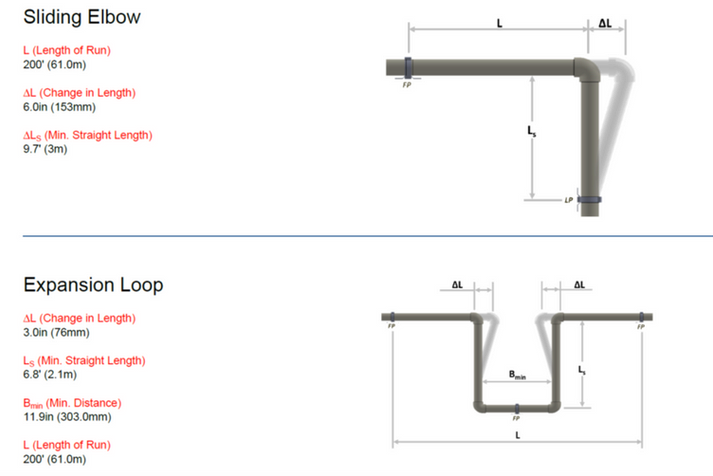
To illustrate this, if 200 feet of 2” SDR 11 polypropylene pipe is installed at 70° F, and the installation is exposed to 100° F ambient temperatures, that 200-foot run will want to grow ~6 inches. Similar but longer growth would be seen in polyethylene pipes.
Asahi/America offers PVDF and ECTFE piping, which grow at ~0.80” and ~0.53” per 10° F Δ T per 100 feet of pipe, respectively.
Again, this same growth would occur if the media temperature changed from 70° F to 100° F. As the example above shows, considerable growth can occur in a thermoplastic process piping system, which needs to be addressed properly.
For single wall piping systems, expansion and contraction can be addressed in several ways; expansion offsets, or expansion loops, could be built into the system to accommodate the movement. Examples of these, based on the polypropylene installation above, are shown here:

If these legs or loops are too large for the location, more than one can be utilized to make the installation more manageable. Moreover, the piping installation itself often offers bends, drops, and turns that can be integrated into “expansion loops” naturally. However, there are times when these devices are just too large or cumbersome to install, and other methods need to be employed. Certainly, expansion bellows, flexible hoses and the like can be used, but they must be compatible with the process media and operating characteristics and conditions. These can also be large and cumbersome.

Another option is to consider an anchored and guided system. Asahi/America offers products in polyolefin and fluoropolymer materials. When conditions allow, these materials can be held firmly in position by restraint fittings and guides. This method utilizes the materials’ natural ductility to accept the stresses generated by the expansion and contraction forces and direct them to the restraint fittings – which act as thrust blocks. The appropriate forces are provided to properly anchor the restraint fitting to the structure.
This method is commonly used in chase, trench, and tunnel installations where loop sand legs are not feasible. It is preferable to install loops and legs, as these tend to minimize induced stress, but in many cases, the anchor and guide method is acceptable.
Calculations can be made to confirm this type of installation.
When working with double containment piping systems, expansion and contraction must be considered, but now, two pipe movements must be analyzed.
The internal carrier pipe is subject to the initial installation temperature and the temperature swings, if any, of the media. This needs to be considered relative to the confined space of the containment pipe, which is subject to ambient temperature swings, if the piping system is installed above grade.
Similar methods can be used to control single wall pipe, but one must consider situations where the carrier pipe may be growing within a containment pipe that may have contracted.

Most double containment systems have a “standard” annular space between the pipes, and this may have to be enlarged (increasing the out-containment pipe size) in order to provide more internal space for the carrier pipe to move. One way to do this would be to direct movement to 90-degree bends and enlarge the outer 90 to accept the internal pipe movement.

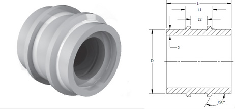
When both inner and outer pipes are the same material, double contained restraint fittings, called Dogbones®, can be used to anchor the inner and outer pipes simultaneously. This allows the designer to treat the double containment growth in a very similar fashion to single wall anchoring and guiding, and minimizes, and possibly eliminates, the need for expansion/contraction loops.
Thermoplastic pipes expand and contract to such an extent that those actions should always be considered, even if they are minimal and non-consequential.
However, there are times when these movements and forces must be accounted for, and we’ve just explored some of the more common ways to address them.
Asahi/America is well-equipped to assist the designer in controlling these forces. There are online tools to assist, such as our expansion calculator, and our technical services team is ready to offer in-depth guidance and component design for special applications.
